Choke Ring Antenna
- Competitive high-end Geodetic Antenna
- Topcon’s TA-5 vertical convex dipole antenna element for full spectrum GNSS signal tracking
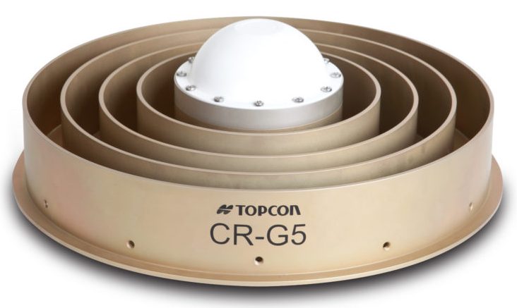
- Topcon designed choke ring ground plane
- Environmentally robust and sealed
- Improved phase center stability in vertical over expanded GNSS frequency band. Improved low elevated satellites tracking
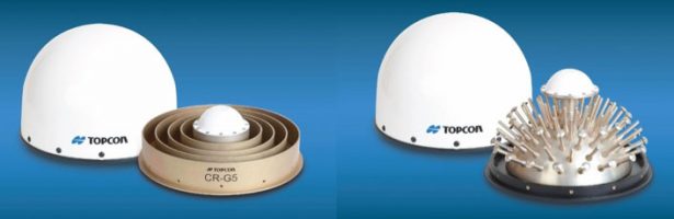
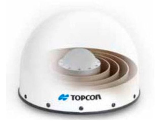
Next Generation Full Wave Geodetic Antenna Anti-Snow Spherical Dome
The CR-G5 is a newly designed choke ring antenna based on Topcon’s new TA-5 full spectrum GNSS antenna element. The TA-5 antenna element utilizes an array of vertical convex dipoles. This new antenna provides Full Wave tracking technology for existing and future GNSS signals. The antenna addresses the evolving requirements for reference networks and infrastructure monitoring applications
Topcon TotalCare
This online resource comes with real live people ready to help. Get expert training from Topcon University’s large collection of online materials, and expert help directly from Topcon Technical Support.
Access software and firmware updates, current publications, and guidance from the experts at Topcon all right from your computer or mobile device.
| SPECIFICATIONS | |
| Dimensions | |
| Antenna without Anti-snow Dome | 380 mm (D) x 155.5 mm (H) |
| With Topcon Anti-snow Spherical Dome | 380 mm (D) x 292 mm (H) |
| With SCIGN Anti-snow Short Dome | 415 mm (D) x 287 mm (H) |
| Weight | |
| Antenna | 4.9 kg |
| Topcon Anti-snow Spherical Dome | 1.1 kg |
| Antenna w/ Topcon Anti-snow Spherical Dome | 6 kg |
| Power | |
| Input Voltage | +3 to +12 VDC |
| Current Consumption | 100 mA (typical) |
| Connector | N-type |
| Environmental | |
| MIL-STD-810G | (Methods 501.5, 502.5) |
| Temperature | -50°C to +70°C |
| Operating Range | -55°C to +85°C |
| Storage Range | 95%, Method 507.5 |
| Salt Fog, 5% | Method 509.4 |
| Vibration | Method 514.6, Broad band noise (random vibration), |
| along each of 3 axes, Category 4, table 514.6C-IV | |
| Mechanical Shock | Method 516.6, along each of 3 axes. Procedure I – Functional |
| Shock, Table 516.6-I, Fig. 516.6-8, accelerative forces up to 40g | |
| IP Rating | IEC 60529 IP67 |
| Drop Test | Repeated drops from the height of 1 m on concrete surface. |
| All sides – top, bottom & border (with Dome) | |
| RoHS Compliant | Yes |
| Performance | |
| Operating Frequency Range | |
| Lower band | 1230 MHz±70 MHz (L5, E5B, E3, L2, G2, E4, E6) |
| Upper band | 1565 MHz±50 MHz (E2, L1, E1, G1, OmniStar, SBAS, CDGPS) |
| Out-of-Band Rejection | |
| Upper band (1568.5 MHz ±150 MHz) | -40 dBc (typical) |
| Lower band (1232 MHz ± 100 MHz) | -60 dBc (typical) |
| Other bands | |
| f < 1000 MHz | -60 dBc (typical) |
| f < 1000 MHz | -60 dBc (typical) |
| LNA Gain | 43 dB (typical) |
| Gain at Zenith (90°) | Lower band: +7.5 dB (typical) Upper band: +5 dB (typical) |
| Gain Roll-Off (from Zenith to Horizon) | Lower band: -16.5 dB (typical) Upper band: -13 dB (typical) |
| Noise Figure | 1.0 dB (typical) |
| VSWR | 1.5 : 1 |
| Differential Propagation Delay (typical) | Lower band: 3 ns (maximum) Upper band: 3 ns (maximum) |
| Nominal Impedance | 50 Ohm |